
Introduction
The Methanation Energy Loop — Manakai → Methane (M→M) Architecture establishes a compact, biologically governed pathway for converting agricultural waste streams into stable, cooking-grade CH₄ at household and community scale. Unlike industrial Power-to-Gas systems, the M→M loop is engineered for micro-nodes: small barns, family clusters, rural households, and localised community hubs. It operates within the Manakai reinforcement–fatigue logic, ensuring coherence, safety, and self-limiting behaviour across biological, thermal, and gas-transfer states. The loop integrates four controlled stages:
- (1) slurry digestion and fugitive-gas capture;
- (2) biological methanation using hydrogenotrophic archaea under Manakai equilibrium control;
- (3) membrane or PSA upgrading to high-purity CH₄; and
- (4) PHM-weighted allocation into household cylinders or local micro-grids.
Each subsystem is sized for minimal footprint, quiet operation, and low ecological overhead, aligning with the Truthfarian ecological doctrine and the NashMark fairness framework. The purpose of this chapter is to formalise the M→M architecture as a deployable, governed unit technically rigorous, biologically stable, and appropriate for small communities without reliance on industrial-scale chemical infrastructure.
Manakai → Methane (M→M) Architecture
1. Source & Pre-Clean
• Covered slurry digester (primary CH₄) + low-pressure barn hoods (fugitive CH₄).
• Knock out H₂S/NH₃ with a biotrickling scrubber so downstream biology stays coherent (microbial gateways).
2. Reconstitute to CH₄ (Biological Methanation)
• Route the cleaned stream (typically 45–65% CH₄ + CO₂) to an ex-situ thermophilic bioreactor seeded with hydrogenotrophic archaea; inject H₂ (from surplus renewables) so CO₂ + 4H₂ → CH₄ + 2H₂O.
• Operate under a reinforcement controller that is the Manakai function with domain-swaps:
$G_{t+1}=G_t(1-\delta-\alpha(t)) + I(\varepsilon,\nu,R,UV)$
Map terms for gas:
• $G_t$ → methanation rate / CH₄ purity
• $\delta$ → baseline microbial performance decay (biofilm aging)
• $\alpha(t)$ → accumulated stress/fouling across cycles
• $I(\cdot)$ → reinforcement vector: ϵ (load noise), ν (buffer state), R (reactor resonance), UV (H₂ feed & heat)
This keeps the same propagation–decay equilibrium idea: push rate when coherence is high; back off into dormancy/maintenance when fatigue rises—so it self-limits instead of running unstable.
3. Upgrade & Store
• Polish with PSA or 2-stage membranes to >95% CH₄ for cooking-gas grade, then buffer in an LPG-style tank.
4. Use PHM & Wireless Stack for Dispatch
• Treat the gas node as an energy source in your Wardenclyffe-2.0 graph.
• Add a biogas/methane edge with PHM ecological cost coefficients.
• Allocate cylinders/heat by NashMark fairness (clinics → elders → food).
Why this is Manakai-true
• Reinforcement as structure, not stimulation.
• Microbial gateways controlling symbiont behaviour.
• Portable control logic (I(⋅) and α(t)) directly maps to biofilm duty-cycles.
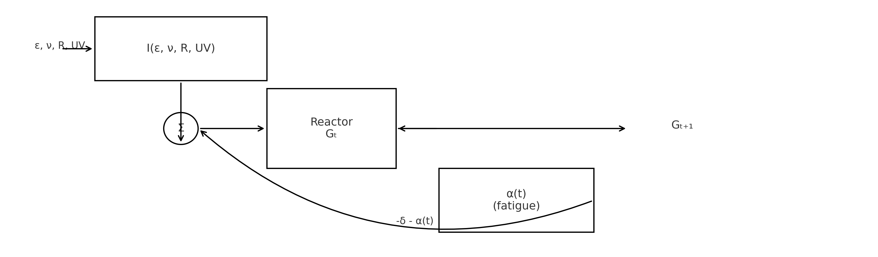
Fig. 1 — Manakai → Methane P&ID Process Flow
5. P&ID + CONTROL LAW (Manakai → Methane Loop)
This formalises the biological methanation loop as a P&ID table and closed control law:
$G_{t+1}=G_t(1-\delta-\alpha(t)) + I(\varepsilon,\nu,R,UV)$
5.1 P&ID (Logical Form)
Node 1 — Source Digester
Inputs: slurry, barn CH₄
Outputs: raw biogas
TI-101, PI-102, AI-103
Control: maintain ±1.5°C
Node 2 — Biotrickling Scrubber
AI-201, pH-202, ΔpH alarm > 0.7
Node 3 — Thermophilic Reactor
TIRC-301, pH-302, ORP-303, GC-304, FI-305
R-CL: pH 7.0–8.2, 55°C ± 2°C
F-CL: α(t) ↑ → H₂ −30%
I-CL: ϵ, ν, R, UV
Node 4 — PSA/Membrane
PI-401, AI-402 → >95% CH₄
Node 5 — Storage
PI-501, TI-502, WC-503
Dispatch: PHM-weighted
| Symbol | LaTeX | Meaning | Operational Range / Notes | Unit |
|---|---|---|---|---|
| Gt | $G_{t}$ | Methanation rate / CH₄ purity | 0.45–0.75 raw; >0.95 upgraded | fraction |
| δ | $\delta$ | Baseline microbial decay | 0.01–0.03 | day⁻¹ |
| α(t) | $\alpha(t)$ | Accumulated stress / fatigue | 0–1; back-off if α > 0.35–0.45 | – |
| I(ε, ν, R, UV) | $I(\varepsilon,\nu,R,UV)$ | Reinforcement vector | Normalised 0–1 | – |
| ε | $\varepsilon$ | Load noise | |Δflow| < 10–15% | m³/h deviation |
| ν | $\nu$ | Nutrient / alkalinity buffer | 3–5 g/L CaCO₃ | g/L |
| R | $R$ | Reactor coherence (pH, T, mixing, av) | pH 7.0–8.2; 55°C ± 2°C | – |
| UV | $UV$ | Energy availability (H₂ feed + heat) | H₂:CO₂ ≈ 4.2:1 | – |
| H₂t | $H_{2,t}$ | Hydrogen feed | Cut −30% on fatigue | NL/min |
| av | $a_{v}$ | Specific surface area | 150–400 | m²/m³ |
| τ | $\tau$ | Dormancy interval | 15–30 min | min |
| αcrit | $\alpha_{\mathrm{crit}}$ | Fatigue threshold | 0.35–0.45 | – |
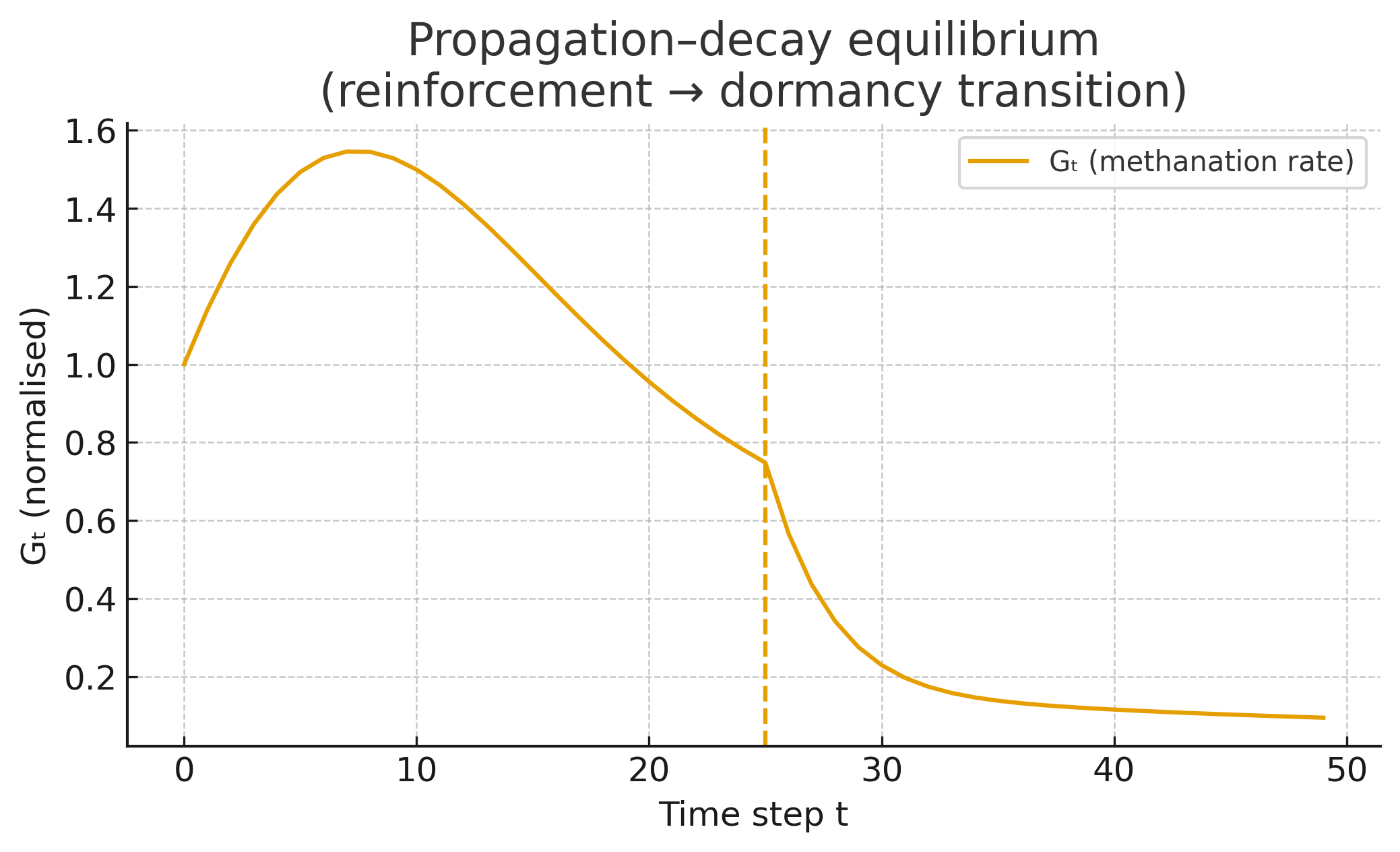
Fig. 2 — Reinforcement + Fatigue Control Law Schematic
5.2 Control Law (Formal Expression)
$x_t=(G_t,T_t,pH_t,H_{2,t},a_v,\alpha(t))$
$I=k_1\varepsilon + k_2\nu + k_3R + k_4UV$
$I^*=\frac{1}{1+e^{-I}}$
$\alpha(t+1)=\alpha(t)+\rho f_{\mathrm{stress}}$
$ \text{if }\alpha(t)>\alpha_{\mathrm{crit}}\Rightarrow H_{2,t+1}=0.7H_{2,t}$
$u^{H_2}_t=\arg\max_{u\in U}[CH_4(u)R-\lambda\alpha(t)]$
$G_{t+1}=G_t(1-\delta-\alpha(t))+I^*$
6. Pilot BOM — Farm-Scale Prototype
6.1 Targets
• Raw biogas: 20–30 m³/day
• Post-methanation: 60–75% → >95% CH₄
• 9–12 kg CH₄/day (450–600 MJ/day)
6.2 Mechanical / Biological Subsystems
• CSTR digester 15–30 m³
• Scrubber
• Thermophilic reactor 500–1000 L
• 2-stage membranes
• Composite cylinders
• Acoustic pulsation LF <20 Hz
6.3 Instrumentation & Control
TIRC-301, pH-302, ORP-303, GC-304, FI-305, AI-201, PC-401
6.4 Electrical / Energy Subsystems
Electrolyser 5–10 kW
48–96 V LFP
Auxiliary heater
NashMark controller
Sentinel module
6.5 Safety & Integration
• H₂ shutdown ΔT > 3°C
• Auto-vent CO₂
• Odorant injection
• PHM fairness hierarchy
7. Atmosphere & Frequency Integration
Macro Layer
Shed-hall acoustics tuned to reduce animal stress; barn coherence is part of R.
Micro Layer
Low-Hz mixing pulses → improved mass-transfer without shear → raises R.
Distribution Ethics
• Add biogas node to NashMark optimisation.
• Minimise ∑cₑ under PHM weights.
• Cooking/heat first → generator feed optional.
8. References
1. Anaerobic Digestion Fundamentals & Co-Digestion
Authority: Appels, L. et al., “Principles and potential of the anaerobic digestion of waste-activated sludge,” Progress in Energy and Combustion Science, 34(6), 2008.
Function: Canonical review of anaerobic digestion principles, process parameters, reactor types, and design methods, including biogas yield baselines.
Application to M→M: Provides the fundamental process envelope and design logic for the covered slurry digester and small-herd biogas production assumptions.
Authority: Rabii, A. et al., “A Review on Anaerobic Co-Digestion with a Focus on the Role of Co-Substrates,” Energies, 12(6), 1106, 2019.
Function: Reviews co-digestion strategies to stabilise digestion and increase biomethane yield across multiple feedstock blends.
Application to M→M: Supports future extension of the Manakai loop to mixed farm wastes and co-digested substrates without altering the control law.
Authority: Walid, F. et al., “Modeling and Optimization of Anaerobic Digestion: A Review,” E3S Web of Conferences, 2021.
Function: Summarises mathematical modelling and optimisation methods applied to AD reactors (kinetics, inhibition, stability).
Application to M→M: Provides external support for representing the digester and methanation reactor as state–transition systems compatible with the Manakai equilibrium formulation.
2. Small-Scale & Farm Biogas Systems
Authority: Wadi, R.M. & Khalifa, S.A., “A Review of Biogas Production from Small-Scale Anaerobic Digestion Plants,” Journal of Engineering and Sustainable Development, 28(4), 2024.
Function: Reviews small-scale, farm-oriented AD plants, feedstocks, and performance benchmarks.
Application to M→M: Supports the chosen pilot scale (single cow shed, 20–30 m³/day biogas) and validates rural deployment assumptions.
Authority: IEA Bioenergy, Task 37 Reports on Biogas from Agriculture and Waste (various issues).
Function: Provides technical guidance on agricultural biogas systems, integration into farm operations, and use of biogas for heat and cooking.
Application to M→M: Underpins the decision to deploy M→M first as a farm-scale cooking and hot-water solution with standardised safety practice.
3. Biological Methanation & Hydrogenotrophic Archaea
Authority: Voelklein, M.A. et al., “Biological methanation: Strategies for in-situ and ex-situ upgrading in anaerobic digesters,” Applied Energy, 2019.
Function: Compares in-situ and ex-situ biological methanation, including hydrogenotrophic archaea and reactor configurations.
Application to M→M: Validates the ex-situ thermophilic reactor design and use of CO₂ + 4H₂ → CH₄ + 2H₂O as the core upgrading reaction.
Authority: Rusmanis, D. et al., “Biological hydrogen methanation systems – an overview of design and operational challenges,” Greenhouse Gases: Science and Technology, 2019.
Function: Reviews biological hydrogen methanation (BHM) for Power-to-Methane and discusses key design and control challenges.
Application to M→M: Provides external corroboration for using surplus renewable H₂ as the reinforcement resource in the Manakai-controlled methanation loop.
Authority: Yörüklü, H.C. et al., “A comprehensive review on biological methanation processes from gaseous feedstocks to biomethane,” Energy, 2025 (in press).
Function: State-of-the-art review on biological methanation pathways, reactor concepts and life-cycle performance.
Application to M→M: Supports the M→M architecture as part of the modern biological methanation family while preserving proprietary Manakai equilibrium logic.
4. H₂:CO₂ Ratio, Power-to-Gas & Technical Integration
Authority: Wahid, R. et al., “Effects of H2:CO2 ratio and H2 supply fluctuation on methane content and microbial community in in situ biological methanation,” Biotechnology for Biofuels, 12:104, 2019.
Function: Demonstrates that a H₂:CO₂ molar ratio near 4:1 is critical for stable biological methanation and high CH₄ content.
Application to M→M: Underpins the control setpoint of H₂:CO₂ ≈ 4.2:1 and justifies embedding ratio management into the reinforcement term and fatigue back-off rule.
Authority: Thema, M. et al., “Power-to-Gas: Electrolysis and methanation status review,” Renewable and Sustainable Energy Reviews, 112, 2019.
Function: Reviews Power-to-Gas architectures, methanation routes, and integration into energy systems.
Application to M→M: Places the Manakai-controlled methanation loop in the broader Power-to-Methane context while demonstrating alignment with recognised PtG topologies.
Authority: Michailos, S. et al., “A techno-economic assessment of implementing power-to-gas to a wastewater treatment plant,” Journal of Cleaner Production, 2020.
Function: Assesses techno-economic viability of integrating biomethanation into PtG systems at real plants.
Application to M→M: Provides external justification for coupling M→M with surplus renewable electricity at the farm or micro-grid level.
5. Biotrickling Scrubbers & Gas Cleaning (H₂S/NH₃)
Authority: Dumont, E., “H2S removal from biogas using bioreactors: a review,” International Journal of Energy and Environment, 6(5), 2015.
Function: Reviews biotrickling filters, bioscrubbers and related bioreactors for H₂S removal from biogas streams.
Application to M→M: Supports the selection of biotrickling scrubbers as the primary H₂S/NH₃ knockout stage before the Manakai core reactor.
Authority: Nhut, H.H. et al., “Removal of H2S in biogas using biotrickling filter: A review,” Biochemical Engineering Journal, 2020.
Function: Summarises performance, design and limitations of aerobic biotrickling filters for H₂S oxidation.
Application to M→M: Informs loading rates, pH control, and performance expectations for the scrubber node in the P&ID.
Authority: Lenis, A. et al., “Implementation of a pilot-scale biotrickling filtration system for hydrogen sulfide removal from biogas,” Processes, 11(2), 2023.
Function: Reports real-scale performance of pilot biotrickling filtration for H₂S removal.
Application to M→M: Supports the field-feasible nature of using pilot-scale biotrickling units at the same scale as the proposed M→M farm loop.
6. Biogas Upgrading: PSA, Membranes & High-Purity CH₄
Authority: Bauer, F. et al., “Biogas upgrading – Review of commercial technologies,” Biomass and Bioenergy, 53, 2013.
Function: Benchmarks water scrubbing, amine scrubbing, PSA, membranes and cryogenic upgrading for biomethane production.
Application to M→M: Validates the choice of PSA / 2-stage membranes as a realistic route to >95% CH₄ purity for cylinder-grade gas.
Authority: Ryckebosch, E., Drouillon, M. & Vervaeren, H., “Techniques for transformation of biogas to biomethane,” Biomass and Bioenergy, 35(5), 2011.
Function: Provides detailed performance data for various upgrading techniques, including methane purity and energy use.
Application to M→M: Supports the expected performance band of membrane and PSA systems matched to the pilot scale.
Authority: Tomczak, W. et al., “Biogas Upgrading Using a Single-Membrane System: A Review,” Membranes, 14(3), 2024.
Function: Reviews single- and multi-stage membrane systems for biogas upgrading, including recent improvements in methane recovery and purity.
Application to M→M: Provides up-to-date membrane performance metrics that support the M→M claim of reaching cooking-grade CH₄ in compact units.
Authority: López, A.F. et al., “From Biogas to Biomethane: An In-Depth Review of Biogas Upgrading Technologies,” Applied Sciences, 14(6), 2342, 2024.
Function: Comprehensive overview of modern upgrading technologies including physical, chemical and biological pathways.
Application to M→M: Positions the Manakai-controlled methanation loop as complementary to physical/chemical upgrading and confirms the industrial context for >95% CH₄ products.
7. Biological Methanation Control, Stability & Modelling
Authority: Treu, L. et al., “Biological methanation for renewable energy storage: A review,” Energy, 2020.
Function: Focuses on stability, control and operational limits of biological Power-to-Methane systems.
Application to M→M: Provides external justification for prioritising stability and controlled dormancy over maximum throughput in the Manakai reinforcement–fatigue design.
Authority: Savvas, S. et al., “The tubular baffled reactor and its potential for the biological Power to Methane process,” Renewable Energy, 2024.
Function: Examines advanced reactor designs for biological PtM with attention to hydrodynamics and gas–liquid mass transfer.
Application to M→M: Supports the use of structured packing and tuned hydrodynamics (mass-transfer $a_v$) in the Manakai core reactor while leaving the reinforcement law proprietary.
Authority: Walid, F. et al., “Modeling and Optimization of Anaerobic Digestion: A Review,” E3S Web of Conferences, 2021.
Function: Surveys mathematical models for AD including dynamic and optimisation-based formulations.
Application to M→M: Confirms that representing $G_t$, $\alpha(t)$ and $I(\cdot)$ within a discrete-time control law aligns with contemporary modelling practice for digestion and upgrading.
8. Process Control, P&ID & Instrumentation Standards
Authority: ISA, “ANSI/ISA-5.1 – Instrumentation Symbols and Identification,” International Society of Automation.
Function: Defines standard instrument tags (TI, PI, AI, FI, PC, etc.) and P&ID notation used in process industries.
Application to M→M: Provides the formal standard behind the TIRC-301, FI-305, AI-201, PC-401 and related symbols in the M→M P&ID.
Authority: Seborg, D., Edgar, T., Mellichamp, D. & Doyle, F., Process Dynamics and Control, 3rd ed., Wiley, 2010.
Function: Core textbook on feedback control, stability, saturation, and constrained operation of chemical and biochemical reactors.
Application to M→M: Provides the conventional control-theory basis for implementing the reinforcement law, fatigue accumulation, and dormancy/back-off behaviour in a process-control framework.
9. Safety, Utilisation & Cooking-Grade Biomethane
Authority: IEA Bioenergy, Task 37, “Biogas Upgrading and Utilisation,” technical reports (various years).
Function: Provides guidance on using biomethane for heat, power and grid injection, including safety considerations and odorisation.
Application to M→M: Supports the public-safety configuration of odorant injection, over-temperature interlocks and low-pressure storage for cooking-grade gas.
Authority: European Committee for Standardization (CEN), EN 16723 series, “Natural gas and biomethane for use in transport and biomethane for injection in the natural gas network.”
Function: Specifies quality and safety requirements for biomethane used in energy applications.
Application to M→M: Provides external quality targets to align the M→M upgraded gas with recognised biomethane specifications, even when initially deployed for local cooking/heat.